Plc 5 1/2 Slot Addressing
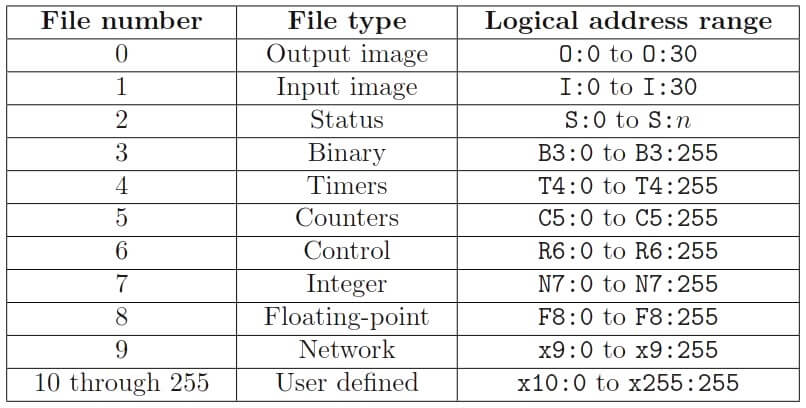
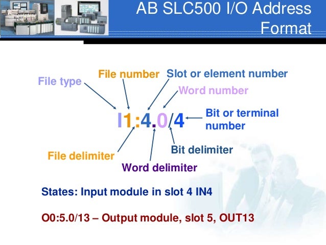
Here it uses Allen Bradley notation for PLC-5 racks. At the top is the location of the input card I:013 which indicates that the card is an Input card in rack 01 in slot 3. Note: Discrete I/O is Not Supported by SLC 5/01 and 5/02. There are a few different formats of addressing that C-more supports when connecting to the Allen-Bradley SLC 500 and MicroLogix PLCs. The Expanded I/O format allows the slot and word to be specified, which is more typical when trying to access Analog I/O data. For example, an address that references an output of a MicroLogix 1100 is O:0/0. That is: O:0/5 means that it is a physical output. O:0/5 means that it uses Slot 0 (in the case of the 1100, this output is onboard) O:0/5 means that it is the fifth output on the PLC. By the way, don’t get the capital “O” confused with a zero.
All EtherNet/IP messages require a path. This is a list of modules (or nodes) that will forward, or process the message (and return the response). This path may be as simple as the IP address of the target device, or may include multiple “hops” from the initial module specified as CIP Id’s or IP addresses.
In any path, the first element is always the device number/IP address relating the DeltaV VIM module to the remote EtherNet/IP module. Any remaining “hops” are specified with two elements for each hop, these elements are the output port of the current module and the address is the identifier of the next module or node. The port is dependent on the module, for an ENBT module, port 1 is the backplane, port 2 is the Ethernet port.

This document will use the rack configuration in Figure 1 as the basis for the examples of how to configure paths in VIMNet Explorer. This setup consists of two ControlLogix IO racks, one with a controller, one (or more) PLC’s on a DH+ network connected to one ControlLogix rack with a 1756-DHRIO module, and two DeltaV Controllers connected to separate ControlLogix Racks with a Generic EtherNet/IP VIM. The message to be used for these examples will be an Unconnected DF1 message (using the Rockwell embedded PCCC commands).
Figure 1 - Example Mixed Protocol PLC Network

Extended CIP Paths are only supported in Generic EtherNet/IP and ODVA EtherNet/IP. Create a VIM placeholder of type I/O VIM – Ethernet IP 4.x or I/O VIM - ODVA EtherNet/IP using the Commission a Simplex Virtual IO Module guide.

Path configurations
Connection 1 Direct Connect
The simplest method is the DF1 connection to a PLC5 using an Ethernet port on the PLC or on an Ethernet side-card (ENET module). This connection has only the IP address of the receiving module required.
This connection is show in Figure 2 with the red line. This connection runs directly from the DeltaV1 VIM Ethernet connection to the PLC5/xxE Ethernet connection, with only a switch between.
Figure 2 - Base Network Diagram with a Direct Connection shown in Red
Add a Device
Start by adding a device to the VimNet explorer IO tree under the card and port desired. Right click on the port and select “Add Device” (Figure 3). The Device properties dialog box (Figure 4) is different for version 4.x, it includes the ability to exclude types of messages connections from selection box for the device, as well as the “Device Extended Address: and DF1 Extended Address elements.
Figure 3 - Add Field Device Context Menu
Figure 4 - Device Properties
Select the Device number for DeltaV and the button to create a new IP address for the device. For this example, the ENBT module is assigned a device number of 1 and IP address of 10.22.6.21 that matches that of the PLC5/xxE module. Selecting to both dialogs will create the device branch on the IO tree.
Plc 5 1/2 Slot Addressing Tool
Add the Connection
Next create a definition of the connection message to the PLC5. This may be done by selecting Add Connection Definition from the Ethernet IP Connection Library branch of the VIMNet tree (Figure 5).
Figure 5 - Connection Library Context Menu
Select either UCMM or Class3 from the Msg Type section of the dialog (Figure 6), make sure DF1 is selected, then enter the message details.
Figure 6 - EtherNet/IP Connection Definition - Message Type
In the message details (Figure 6) select the processor, type access type, and service type required as well as the file parameters. For a direct connection to a PLC5, the “Slot Address” check box should be un-checked. This makes the PLC IP address for the device this is added to the final destination. Finally, select OK to the dialog, then on the device configured above, select the context menu option “Add Connection”, select this library definition and OK to place it in the IO tree.
Connection 2, slot addressing
Next in simplicity example is that of a DF1 connection From DeltaV 1 to the Logix 5000 controller in slot 0 of rack 1 via the ENBT module in slot 2 (IP address 10.22.6.55). This requires only one “hop” from the ENBT module to the controller over the rack backplane.
This connection is show in Figure 7 with the red line. This connection runs from the DeltaV VIM Ethernet connection through the switch to the ENBT card in chassis 1, then finally over the backplane to the Logix controller in slot 0.

Figure 7 - Base Network Diagram with Single-hop Slot Addressing Path shown in Red.
There are two methods to connect with the controller, one is to address the final slot in the connection definition, the other in the device definition.
Either of these methods will work with the generic firmware 4.1.5 or above. If all connections to a device are expected to be to the same address, then the “Device Definition Addressing” method will be simplest to use. If the device specified will have other connections attached that are addressed to different slots, then the “Message Definition Addressing” method allows individual slots to be assigned to each connection message under the device.
Message Definition Addressing
The first, all of the configuration steps in this may be the same as the simple direct connection to the PLC5/xxE above, except for the last step of configuring the message parameters (Figure 6) where the Slot is enabled and set to 0, since the CPU is in slot zero of the chassis. Port is set to 1 for accessing the chassis backplane.
Device Definition Addressing
The second method (requires firmware 4.1.5 or above and VIMNet Explorer 9.0.12.6 or above) uses the same message configuration as the PLC5/xxE (i.e., no slot address at the connection level) but uses the device properties dialog to specify the address that will be used for the connection. For this just open the device properties dialog (Figure 8) and enter a 1,0 in the Device Extended Address field. The first parameter specifies the ENBT port backplane, the second the ID of the slot that will be addressed. The parameters are separated by a comma.
Figure 8 - Device Properties with a Single-Hop Extended Address
Connection 3, network hops
If there is not a direct Ethernet connection to the target device, such as from DeltaV 2 to the ControlLogix in rack 1, then the use of the ControlNet bridge may be used for the connection. This requires four “hops” in the connection. This method requires firmware 4.1.5 or above and VimNet Explorer 9.0.12.6 or above.
This connection is show in Figure 9 with the red line. The first step is from DeltaV 2 to the ENBT module in slot 1 of rack 2. This is similar to the normal EtherNet/IP connection used in Connection 1.
Figure 9 - Base Network Diagram with a Multi-Hop Network Path shown in Red
Next the message is directed to slot 3 (ControlNet module 2), and to ControlNet module 1 in rack 1 over the ControlNet network. This requires two hops and is configured using the device properties dialog in the same manner as Connection 2.
Note: For ControlNet, RSNetworx for ControlNet is required for configuring the connections in the Logix configuration utility.
The Device Extended Address for the two intermediate hops will be 1,3,2,11 where 1 directs the message to the backplane of the rack from the ENBT, then to slot 3 (the ControlNet module), and then over ControlNet (port 2) to the ControlNet module in rack 1 (address 11).
Figure 10 - Device Properties with a Multi-Hop Extended Address
An alternative path would be from the ENBT module to the ENBT module on the same subnet as rack 1 then via EtherNet/IP to rack 1. This path would be 1,0,2,10.22.6.55. This path dissects as packplane port of the ENBT to slot 0 of the rack (ENBT module 3), then over EtherNet/IP port (2) on the ENBT, and over Ethernet to address 10.22.6.55 (ENBT module 1 in rack 1).
The final hop is to slot 0 in rack 1 over the backplane. This may be configured using either of the methods from Connection 2, slot addressing. If Device Definition Addressing is used, then the format in the device properties dialog Device Extended Address will be either 1,3,2,11,1,0 or 1,0,2,10.22.6.55,1,0. If the Message Definition Addressing approach is used, then the address in the device properties is left as is and the slot is addressed in the individual messages.
Plc 5 1/2 Slot Addressing System
Connection 4, DH+ Extensions
To create a connection to remote PLC’s (either PLC5’s, or SLC’s) using the 1756-DHRIO module (shown in Figure 11 rack 1 slot 6), requires a single hop from DeltaV 1 using a similar configuration as Connection 2 but with slot 6 as the final address. From DeltaV 2 the same addressing as connection 3 is uses, with final CIP address being slot 6 rather than the controller in slot 0. This method requires firmware 4.1.5 or above and VimNet Explorer 9.0.12.6 or above.
Figure 11 - Base Network Diagram with DH+ Extensions
To address the PLC over the DH+ network, the message must be adapted to use Class3 messages to the DHRIO module (Figure 12), and in the Msg Details dialog select the DHRIO ‘A’ or DHRIO ‘B’ service to access the “A” or ”B” ports on the module (Figure 13).
Figure 12 - EtherNet/IP Connection with Class 3 DF1 Messaging Selected
Figure 13 - Class 3 DF1 Message Parameters
Finally, the DH+ address must be specified at the device level (device properties dialog). To add the DH+ addressing, check the DF1 Extended Address check box (Figure 14), then enter the node number on the DH+ network to access (3 in this example).
Figure 14 - Field Device Properties with DF1 Extended Addressing Enabled
Introduction to the PLC-5 Chassis
The PLC-5 Chassis is the device which holds modules. In the PLC-5 system, we will first configure several switches for the desired operation. In this post, we’ll walk through each switch setting for both a PLC-5 Processor, and a 1771-ASB. Another key point is that the chassis comes in 4 sizes: 4-slot, 8-slot, 12-slot, and 16-slot. Shown Below is a 4-Slot chassis. Notice the slot for the processor does not count as an I/O Slot.
The first thing to remember is that the chassis is not called a “rack” in the PLC-5. The chassis holds modules, whereas a rack is a memory location in the processor.
DIP switches
Plc 5 1/2 Slot Addressing Machine
On the backplane, you see 8 Dip Switches. These switches configure the chassis for the desired operation.
In this case, we have 8 “Rocker” Switches. If we press a switch in on the left, the switch is off. In like manner, if we press a switch in on the right, it’s on. It’s important to remember to not use a pencil point when setting these switches. The graphite could cause the switch to be permanently on.
For a PROCESSOR in this chassis:
Switch 1: Last State — If this switch is ON, the outputs of the chassis will stay in their last state if a hardware failure occurs. Otherwise, they are shut off.
Switch 2 and 3: Always Off — If a processor resides in this chassis, we do not use these two switches. However, these switches could be used if an adapter or PLC-2 processor was in this slot.
Switch 4 and 5: Addressing Mode — The addressing mode tells the processor how many slots equal a group of memory. (A group 16 bits of input and 16 bits of output). If both switches are OFF, every 2 slots equal a group (2-slot addressing). With 4 off and 5 on, every slot equals a group (1-slot addressing). When 4 is on and 5 is off, every 1/2 slot equals a group. (1/2 slot addressing) — Both switches ON is an invalid setting.
Switch 6 and 7: EEPROM Transfer — If you use an EEPROM as an onboard backup of your project, we will need to decide the conditions in which we need the EEPROM to load. With 6 and 7 off, the EEPROM will load at power-up. With both switch 6 and 7 on, the EEPROM will load only if the processor memory is invalid. If there is no EEPROM, or we wish to load the EEPROM manually, turn 6 on and 7 off.
Switch 8: Memory Protect — Turn this switch ON to enable memory protection. This will prevent a user from downloading to the processor, or performing an online edit. Normally, we’ll leave this switch OFF, and memory protection is disabled. This allows us to make changes to the project as we need.
For an ADAPTER in the chassis:
Realize that these settings are different than for a processor. You must take important care to use the correct chart for the settings of your chassis.
Switch 1: Last State — This is for the last state of the outputs if a communication fault occurs. In this situation, leave switch 1 off. The outputs will be turned off if a communication loss is detected. This is usually the recommended setting. If you turn on Switch 1, the outputs will remain in the last state if a communication loss occurs.
Switch 2: Processor Restart Lockout — If this switch is off, the processor will not restart the chassis if a communication loss occurs. You must physically reset the chassis with a reset button on the adapter, or cycle power. When this switch is on, the processor can restart the chassis when communication is restored.
Switch 3 and 4: Always Off — These switches are not used for an Adapter in the chassis. These switches are used for other purposes.
Switch 5 and 6: Addressing Mode — For 2 slot addressing, shut off both switches. Turn switch 5 on, and 6 off, to select 1 slot addressing. Set 5 off, and 6 on for 1/2 slot addressing. Both switches on is an invalid setting.
Switch 7 and 8: Always off — Again, we do not use these if an adapter is in the chassis.
Power Supply Jumper
It’s important to remember the power supply jumper. When you use a slot mounted power supply, such as the 1771-P4S, the jumper is in the Y position. However, if you use an external power supply, such as the 1771-P7, set the jumper to the “NO” position.
Plc 5 1/2 Slot Addressing Machines
To verify the accuracy of this information before implementing it in any way, consult the PLC-5 Quick Reference Guide. this is an invaluable tool to have when setting up a chassis!
For other information on the PLC-5, visit the PLC-5 Category Page!
— Ricky Bryce